

Medium-voltage switchgear maintenance: tests and frequency
Tests included in MV switchgear and LV switchboard maintenance: insulation, current injection, opening and closing times, pole simultaneity and interlocks.
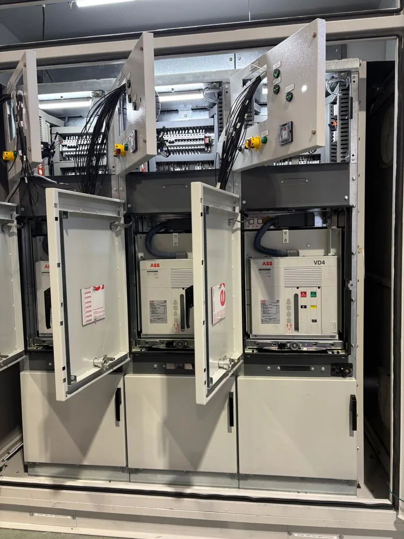
Maintenance of a medium-voltage switchgear cubicle consists of verifying, with instruments, that the circuit breaker opens and closes within the correct time, that the three phases operate simultaneously, that the insulation of the busbar system and cables retains its value, that the protection relays trip at the current they were set for, and that the interlocks prevent hazardous operations. It is carried out with the cubicle de-energized and locked out, and the usual frequency is annual for the general inspection, with complete electrical testing every two or three years or as indicated by the manufacturer and the criticality of the process.
Why does medium-voltage switchgear need maintenance?
An MV cubicle is both a mechanical and an electrical piece of equipment. The circuit breaker has springs, mechanisms and contacts that wear with every operation; the insulation ages with temperature, humidity and contamination; the relays depend on control wiring that can loosen. None of these degradations is visible from the front of the cubicle, and all of them can end in a fault that is not cleared or in an internal arc.
Tests included in MV switchgear and LV switchboard maintenance
Insulation measurement
DC voltage is applied with an insulation tester (megohmmeter) between phases and between each phase and ground, on power cables and the busbar system. A low value or a downward trend between maintenance intervals indicates moisture, contamination or deterioration of the dielectric. The temperature is recorded so that readings from different years can be compared.
Closing and opening tests
The circuit breaker is commanded to close and open from local and remote control, verifying that the mechanism responds, that the spring charges and that the indications reflect the actual state. This is the basic functional test and it reveals weak trip coils, jammed mechanisms and miscalibrated auxiliary contacts.
Opening and closing times
A circuit breaker analyzer measures the time between the command and the movement of the main contacts. A slow breaker takes longer to clear the fault and subjects the system to more energy. The value is compared with the manufacturer's data and with the record from the previous maintenance.
Pole simultaneity
The time difference with which the three poles open or close is measured. If one phase leads or lags more than tolerated, overvoltages and asymmetrical stresses are generated in the transformer and in the loads. Simultaneity is corrected by adjusting the mechanism.
Current and voltage injection
Secondary current is injected into the protection relays to confirm that they trip at the set value and within the set time, and voltage is injected into the metering circuits to verify the instrument readings. It is the only way to confirm that the protection works without causing an actual fault. On LV switchboards with electronic trip units, the injection is performed on the trip unit.
Point-to-point wiring check
Every control, metering, protection and auxiliary services conductor is traced against the drawing, verifying continuity, tightness and labeling. Many nuisance trips and many protections that "did not trip" are explained by a loose terminal.
Mechanisms and interlocks
The circuit breaker mechanism is inspected (lubrication, springs, contact wear) and the electrical and mechanical interlocks are tested: the breaker cannot be racked out while closed, the grounding switch cannot be closed with the circuit energized, the door does not open with the cubicle in service.
How often should each test be performed?
| Activity | Indicative frequency |
|---|---|
| Visual inspection, cleaning, retightening, thermography | Annual |
| Closing and opening tests and interlocks | Annual |
| Insulation measurement | Annual or every two years |
| Timing, simultaneity and relay injection | Every 2 – 3 years, or after a cleared fault |
| Major mechanism overhaul | According to number of operations and manufacturer's recommendation |
These frequencies are indicative. Environments with dust, salinity or high humidity, installations with frequent switching and processes that cannot tolerate shutdowns justify shorter intervals. The circuit breaker manufacturer's recommendation prevails.
What must be documented
- Measured values of insulation, timing and simultaneity, with date and temperature.
- Relay settings before and after the intervention.
- Findings, corrections applied and pending items.
- Comparison with the previous maintenance to detect trends.
A continuous record turns maintenance into information: it makes it possible to anticipate the replacement of a circuit breaker before it fails, instead of reacting afterward.
Maintenance and commissioning
The same tests are applied, in greater depth, during the pre-commissioning and commissioning of a new cubicle or switchboard. That is the moment to establish the baseline values against which all subsequent maintenance will be compared. Details of the scope are in our LV switchboard and MV switchgear maintenance line.
If your installation has switchgear or switchboards without a recent test record, write to us on WhatsApp with the make and type of circuit breaker. We will coordinate the visit and the test plan around the shutdown windows of your process.
QUESTIONS ON THIS TOPIC
How often should medium-voltage switchgear be maintained?
Inspection, cleaning and functional tests every year; complete electrical tests (timing, simultaneity, relay injection) every two or three years or after a cleared fault. Harsh environments justify shorter intervals.
What is the pole simultaneity test?
It measures the time difference with which the three phases of the circuit breaker open or close. A difference greater than tolerated generates overvoltages and asymmetrical stresses in the system.
Can a protection relay be tested without causing a fault?
Yes. Secondary current is injected into the relay with a test set and it is verified that it trips at the set value and within the set time.
RELATED ARTICLES
GE to ABB breaker cross-reference: replacement guide
Technical guide to replacing a discontinued GE breaker with its ABB equivalent: poles, rated current, kA, voltage, mounting and trip curve, checked one by one.
Read article →
ABB molded-case breakers: A2A series vs XT family (XT5N–XT7S)
When to use an A2A breaker up to 250 A and when to move to the XT family up to 1600 A: TMF, TMA and Ekip trip units, terminals and mounting explained.
Read article →
How to select a thermal-magnetic breaker for your panelboard
Ampere rating, poles, interrupting capacity, trip curve and coordination with the conductor: the five criteria for selecting a breaker on 120/240 V systems.
Read article →